
Dredge No. 4 National Historic Site
Klondike National Historic Sites
Reasons for National Historic Significance
Dredge No. 4 is commemorated because it represents the importance of dredging operations in the Yukon between 1899 and 1966. Dredges were brought to the Yukon in 1899 as a very efficient means of mining for Klondike gold. Corporate mining played a major role in the viability of the community of Dawson City and the Yukon Territory.
Background

During the early years of the Klondike Gold Rush, more than 30,000 miners hand mined for gold on the rich placer creeks. Much of the gold was simply too difficult and expensive to remove using hand mining techniques. While hand miners were working hard, promoters and investors were looking for long-term mining possibilities in the Yukon.
In September 1898, the first dredge began working the Yukon River. Promotion of the Klondike fields brought in two large companies, the Canadian Klondike Mining Company in 1905 and the Yukon Gold Company a few years later.
Large land holdings, called concessions had to be available to the corporations. Through negotiations with the Federal Government, the first concession was granted in 1900 to Joe Boyle. The corporations constructed hydroelectric power stations to supply a reliable and consistent supply of power to run the dredges. They constructed a system of dams and ditches to provide an adequate supply of water for the dredges.
Dawson City was the key to the success of the efforts of the large corporations. It could provide government administration and banking services. The transportation network, of rail and steamship, that ended in Dawson City, ensured that the companies could receive the supplies of machinery that were needed to operate. Dawson City also provided a large labour force and suppliers and services to meet the corporate mining needs.
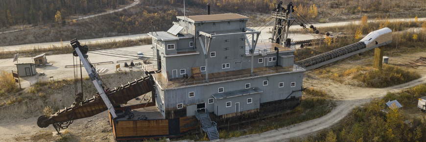
Dredge No. 4 built in 1912 for the Canadian Klondike Mining Company, was the largest wooden hulled bucket lined dredge in North America. It worked in the Klondike Valley on the "Boyle Concession" until 1940 and then was relocated to Bonanza Creek and worked this valley until 1959.
At the peak of corporate mining, a dozen dredges, churned through the creeks. Dredging continued in the Klondike until 1966, when the last of the Yukon Consolidated Gold Company's dredges shut down. Dredge No. 4 represents the many decades of corporate mining in the Canadian mid-north through the 20th century.
Operational history

Summary
Dredge No. 4 commenced operations in May of 1913, and dug its way upstream in the Klondike Valley into what was known as the "Boyle Concession," sinking there in 1924. In 1927, it was refloated and continued to operate from the Klondike Valley to Hunker Creek. The ground at the mouth of Hunker Creek was so rich the dredge produced as much as 800 ounces of gold in a single day on Claim 67 Below. It operated until 1940. The dredge was rebuilt on Bonanza Creek by the Yukon Consolidated Gold Corporation and from 1941 to 1959 worked the Bonanza Creek valley. One of the two dozen dredges that worked this area, Dredge No. 4 rests on Claim No. 17 Below Discovery on Bonanza Creek near the spot where it ceased operations in 1960.
Milestones
1898
The first dredge began operating in the Yukon.
1899
Promoters negotiated with the Canadian government for large tracts of land
1900
Joe Boyle from Woodstock Ontario, was granted 40 square miles of land.
1905
Canadian Klondike Mining Company managed by Joe Boyle, built their first dredge.
1906-1925
The Yukon Gold Corporation operated nine dredges.
1909
Yukon Gold Corporation built the Twelve Mile ditch to provide water for hydraulic mining.
1911
North Fork hydro power plant was in operation and supplying electricity to run all of the dredges.
1912
Canadian Klondike Mining Company Dredge No. 4 was built.
1921
Canadian Klondike Mining Company went bankrupt.
1923
The Yukon Consolidated Gold Corporation was formed and they were the only company until 1966.
1940
Dredge No. 4 was relocated to Bonanza Creek.
1959
Trapped by increasing labour costs, shrinking gravel reserves and the fixed price of gold, Yukon Consolidated Gold Corporation shuts Dredge No. 4 down.
1966
The last of the four operating dredges are shut down, ending Yukon Consolidated Gold Corporation's mining operations in the Klondike.
1970
Parks Canada acquired Dredge No. 4
1997
Dredge No. 4 was designated a national historic site
How it worked

In brief
The dredge was electrically powered from the Company's hydro plant on the Klondike River 48 kilometres (29 miles) away, requiring 920 continuous horsepower during the digging operation. Extra horsepower was needed occasionally for such things as hoisting the "spud" (pivot) and the gangplank.
The dredge moved along on a pond of its own making, digging gold bearing gravel in front, recovering the gold through the revolving screen washing plant, then depositing the gravel out the stacker at the rear. A dredge pond could be 91 metres (300 feet) by as much as 500 feet (152 metres) wide, depending on the width of the valley in which the dredge was working. The operating season was on average about 200 days, starting in late April or early May and operating 24 hours a day until late November.
Specifications
Dredge No. 4 is 2/3 the size of a football field and 8 stories high. It has a displacement weight of over 2,722 tonnes (3,000 tons), with a .45 cubic metre (16 cubic foot) bucket capacity. The dredge could dig 17 metres (48 feet) below water level, and 5 metres (17 feet) above water level using hydraulic monitors and washing the gravel banks down.
Experience what it would have been like as a piece of gold traveling through Dredge #4 from bucket line to tail stacker in this animated video:
Gold Path Animation - Inside Dredge No. 4
Transcript
soft peaceful music aerial view of Dredge No. 4 and the Klondike GoldfieldsDredge No. 4 National Historic Site
From 1898 to 1966 floating dredges dug through the creeks of the Klondike region searching for gold.
historic image of dredge tailing piles
You're about to go inside Dredge No. 4 and see how these giant machines worked
Medium shot in front of the dredge
Dredge No. 4 is a gold mine mounted on a floating barge
Camera moves forward to see a view of the front of digging ladder
Gold-bearing gravels are brought aboard with the digging ladder
The image moves up the digging ladder showing the chain of 66 buckets
that supported a chain of 66 buckets
A view on top of the digging ladder looking into the dredge interior
that could hold over 800kg of rocks each.
The bucket line was removed at the end of every season for maintenance
At the centre of the screen a large sprocket is visible at the top of the digging ladder
The big sprocket is attached to the motor that turns the bucket line
A large metal cross brace is visible as the view moves forward into the dredge interior
The bracing structure is a modern addition
The image moves down to show how rocks fall into a large opening called the hopper
The buckets empty into the hopper, which funnels everything into
The image moves down and forward to show a large rotating metal drum with holes evenly spaced
the trommel, a rotating screen that separates the gold from the gravels using plenty of water
The view moves through the trommel and slides sideways through the metal holes
Fine particles of gold pass through the holes in the screen
The view slides sideways through the long straight wooden structures called sluice tables.
and are caught in the riffles in the sluice tables here
The image moves forward through a long metal ramp and slides out the back of the dredge
The water and fine sand flow off the back of the dredge and into the pond
The view exits the dredge at the exterior of the vessel, the conveyor belt is visible in the top left corner
Rocks larger than the holes in the screen are carried off by the conveyor belt
Virtual tour
Keyboard actions
Key
Action
- A
- Start Tour
- Right
- Next Slide/Panorama
- Left
- Previous Slide/Panorama
- M
- Toggle Map
- G
- Open Close Glossary
- I
- Open Close Instructions Panel
- P
- Play (Auto-Rotation)
- S
- Stop (Auto-Rotation)
- F
- Toggle Full Screen
- B
- To go to the Beginning
- C
- To go to the Conclusion
- Z
- Zoom in
- O
- Zoom out
Transcript
Slide 1
Landing Page Image Description
A view of the dredge looking forward and down at the bow gantry. Click here or press A to start.
Slide 2
Instruction Landing Page Image Description
A grey background with white text boxes.
How to Navigate this Virtual Tour
The instructions and glossary windows are available at any time during the tour by clicking on the appropriate icon on the navigation bar.
Click with the left mouse button or use the keyboard left and right arrow keys to navigate between slides.
The historic images on the introduction and conclusion slides can be enlarged by clicking on them or by typing the number keys shown below the images.
Use the left mouse button, with a click and hold motion to pan around, up and down each of the 360 degree panoramic images. You can also zoom in and out on the panoramas with the mouse wheel.
The high detail, high resolution photographic elevations are accessible by clicking on the icon shown in the selected panoramas, or by navigating to the final 4 slides of this tour. They are zoomable with the mouse wheel.
Any red highlighted text in the panoramas is intended to draw your attention to a highlighted item in the panorama. To find it, hover around the image near the arrows with your cursor.
Glossary of Commonly Used Terms
- Placer Mining
- the mining of stream bed (alluvial) deposits for precious metals. Unlike a hard-rock gold mine, the precious metal is already ‘loose’ in the ground and requires only the action of water and gravity to separate. The principle is the same with a gold pan as with a dredge.
- Riffles
- are devices used to trap gold in a sluice. Can be made of iron (most common), wood, or stone, positioned to allow gold to collect between them.
- Sluice
- A long, narrow trough with riffles on the bottom, through which gravel is washed with water to recover gold. The dense gold is caught in the riffles.
- Sluice Table or Deck
- is a series of sluices side by side.
- Stacker
- A conveyor belt for stacking up tailings away from the dredge, so that they don’t interfere with its operation.
- Tailings
- are the materials left over after the process of separating the valuable fraction from the uneconomic fraction of an ore.
- Trommel
- a rotating screen with constant flow of water for separating placer gold from gravels.
Slide 3
Introduction Page Image Description
A grey metal textured background with eight black and white pop up historical images at the top.
Image 1: Dredge No. 4 buried in silt.
Image 2: Dredge in operation.
Image 3: Dredge control levers in the control room.
Image 4: Thawing operations ahead of the dredge.
Image 5: Bucket line with gold bearing gravel.
Image 6: Tailing piles after dredging.
Image 7: Buckets being lowered into place.
Introduction Interpretive Text
Gold was discovered on Gah dëk (later Bonanza Creek) in August 1896, sparking a massive influx of gold seekers into Tr’ondëk Hwëch’in territory. The colourful scenes of the Klondike Gold Rush soon faded as the thousands of newcomers exhausted the gold deposits that could be mined by the simple tools available to them. Improvements in transportation and civic administration made the Klondike goldfields more attractive to outside investors who moved to secure large tracts of land and put large machines such as this dredge to work on them. The history of the Klondike goldfields illustrates the evolution from labour-intensive hand tools to capital-intensive machines in a remote region. Meanwhile, the lives of the Tr’ondëk Hwëch’in were forever altered, as they were displaced from their lands, waters and traditional harvesting areas, all for a substance which was of no use to them.
A dredge is akin to a large washing machine for gold-bearing gravel mounted on a barge, floating in a pond of its own making. The dredge scoops up material by means of a continuous line of buckets wrapped around a digging ladder. All this material is passed through a rotating screen with a constant flow of water, which separates the gold and fine silt from the larger gravels. The heavy gold is caught in the sluice tables below. The waste gravels, or tailings, are deposited far away from the pond by a conveyor belt assembly called the stacker. The dredge swung around in an arc, taking up the gravel in front and leaving behind the distinctive fan-shaped tailings that are still visible today.
Dredge No. 4 was completed on May 20th, 1913, at a cost of nearly $400,000. By the end of its first season, it had recovered nearly the entire cost of its construction and made a profit. This enormous machine was at the center of a vast enterprise to keep it running. The electrically-powered dredge was supplied from a power plant nearly 70km away, and the water to strip and thaw the overburden and permafrost gravels came from 115 km away in the Ogilvie Mountains.
Slide 4
360 Image Description
Standing next to the dredge on the right side, the entire dredge is visible with disconnected buckets in the foreground.
Slide 5
360 Image Description
Standing next to the dredge on the right side looking back toward the stern. A camera popup icon is visible at the stern.
Interpretive Text
The Dredge floated in a pond of its own making, digging up material from the front in a wide arc and depositing waste rocks – called tailings - behind. The workers would board the dredge by a gangplank suspended from the bow gantry.
Popup
A high resolution view of the dredge from the starboard side. Press R to return to the tour.
Slide 6
360 Image Description
Standing on the right side of the bow the metal digging ladder can be seen outlined in red.
Interpretive Text
Just like a chainsaw with buckets for teeth, the 32.6m (107.1ft) long digging ladder, hinged at the rear, supports the bucket line. It is removed at the end of every season of work for repairs.
Slide 7
360 Image Description
Looking out from above the digging ladder the bow gantry and cables can be seen.
Slide 8
360 Image Description
A view from the interior of the dredge looking toward the bow, the Bucket Line is clearly visible.
Interpretive Text
The Bucket Line is a chain of 66 buckets, each weighing 2100kg and each capable of lifting over 800kg of gravel. Each minute, the digging ladder lifted up as much gravel as three men could shovel in a whole day.
Slide 9
360 Image Description
A close up view of a 14-ton metal sprocket at the top of the digging ladder.
Interpretive Text
The bucket line turns on this 14-ton sprocket, known as the Upper Tumbler. The buckets empty overhand into the hopper just below.
Slide 10
360 Image Description
Looking down from above the sprocket into the interior of the hopper.
Interpretive Text
This would be a very unsafe place to stand while the dredge was in operation – every 3 seconds, a bucket would dump its 800kg of gravel here!
Take a moment to peek at the view from above.
Slide 11
360 Image Description
Standing on top of a metal structure looking down and left you can see the large bucket line drive motor.
Interpretive Text
The bucket line drive motor is mounted high in the Dredge, from here it is 5 storeys to the ground!
Slide 12
360 Image Description
A view from the inside of the trommel looking from front to back, with a water pipe visible at the top of the drum.
Interpretive Text
The Trommel (German for “Drum”) is a rotating, perforated cylinder, 15.3m / 50’ long and 3m / 9’9” in diameter. The water pipe suspended inside sprays water into the trommel to ensure the gravel is well washed and all the lumps broken up.
Slide 13
360 Image Description
Standing at the back of the trommel the exit path to the conveyer belt can be seen.
Interpretive Text
The trommel, by washing and agitation, separates the fine sand and heavy gold from the larger tailings. Anything larger than the holes (6mm-37mm, or two fingers held together) flows out the lower end and is carried away on a conveyor belt, called the stacker.
Slide 14
360 Image Description
Standing at the rear of the trommel a wooden platform can be seen where a crew member would stand.
Interpretive Text
Here the stern decker monitored the flow of gravel off the dredge; a blockage here could mean rapid disaster as the piling rocks could unbalance the dredge.
Slide 15
360 Image Description
A view from the stern of the dredge looking back over a large conveyer belt at the back of the vessel.
Slide 16
360 Image Description
Standing at ground level at the rear of the dredge, a large conveyer belt can be seen from the side outlined in red.
Interpretive Text
As the dredge swings in its digging arc, the tailings are deposited via this 40m/130ft conveyor belt in a similarly arc-shaped pattern. You can also see the outlet of the sluice decks on either side of the stacker, where water and fine silt are returned to the dredge pond.
Slide 17
360 Image Description
Standing at the rear of the trommel a wooden platform can be seen where a crew member would stand.
Slide 18
360 Image Description
Standing inside the dredge, looking from the rear toward the bow, a series metal distributors and sluice tables can be seen.
Slide 19
360 Image Description
A close up view of the exterior metal wall that separates the trommel from the room where the sluice tables are located.
Interpretive Text
The trommel spins just on the other side of this metal wall, which funnels the fine sand and gold into the distributor box below. The water sprayed into each compartment washes everything onto the sluice tables, which were laid with coconut fiber matting with steel riffles on top to catch the gold.
Slide 20
360 Image Description
Standing on the port side of the sluice table room, looking toward the trommel, metal rows of sluice tables can be seen outlined in red.
Interpretive Text
75% of the gold was recovered in the first 1.25m (4ft) of matting, with another fifth concentrated in the distributor. The gold would be ‘cleaned up’ twice a week, or as often as twice a day when the dredge worked particularly rich ground.
Slide 21
360 Image Description
Metal elevator chutes can be seen in the floor at the stern of the sluice table room.
Interpretive Text
The fine sands found on Bonanza Creek would silt up the dredge pond, impeding the dredge’s movement. The sand elevator chutes you see here carry the fine silt and sand to a bucket chain and dumps it onto the stacker with the larger gravels.
Slide 22
360 Image Description
A return to the right bow of the dredge with the digging ladder visible.
Slide 23
360 Image Description
A view of the dredge interior from the starboard side looking from bow to stern.
Slide 24
360 Image Description
The winch battery with large metal gears and control rods can be seen outlined in red.
Interpretive Text
The dredge is moved by means of this winch battery, which control the 2 bow and 2 stern cables and the spuds (anchors). The control rods reach up to the control room high above.
Slide 25
360 Image Description
Standing next to the winch battery and looking toward the stern, the interior of the dredge can be seen.
Slide 26
360 Image Description
A high water mark of discolouration is visible on the metal walls and wooden beams of the dredge interior.
Interpretive Text
In April 1960, Dredge #4 was wrecked by the collapse of the Upper Bonanza dam upstream. Everything you see on this deck was buried in silt for 30 years until the Dredge was refloated and moved to its current position in 1991. Can you spot the high water mark on the walls?
Slide 27
360 Image Description
Standing from above a view of an opening in the deck can be seen with a ladder leading down into the hull.
Slide 28
360 Image Description
Standing inside, the lower hull of the dredge a metal boiler can be seen.
Interpretive Text
This boiler provided heat for the machinery via steam pipes going through the vessel. The boiler was supplied with wood using the small track and cart you can see along the bulkhead.
Slide 29
360 Image Description
Standing in the lower hull, the metal boiler and ladder leading to the upper decks are visible.
Slide 30
360 Image Description
Standing inside, the hull, two large metal tanks are visible.
Slide 31
360 Image Description
Standing inside the hull, a large cylindrical ballast tank is visible outlined in red.
Interpretive Text
The hull contained large ballast tanks which helped keep the dredge afloat evenly.
Slide 32
360 Image Description
An interior view of the hull, ballast tanks, and supporting wooden braces.
Slide 33
360 Image Description
A view of the ladder leading from the lower hull to the upper decks.
Slide 34
360 Image Description
A return to the top of the ladder looking down into the lower hull.
Slide 35
360 Image Description
Standing on the main deck looking at the aft, metal pipes, spare parts and cables can be seen.
Interpretive Text
The aft portion of the main deck was used as an ad-hoc repair shop and spare parts repository. We can also see the cables for moving the dredge along the deck; note the grooves they wore in the planks.
Slide 36
360 Image Description
At the rear of the main deck large metal cables and pulleys can be seen on the floor.
Slide 37
360 Image Description
Looking toward the port side of the dredge, large metal bracing and materials can be seen at the rear of the main deck.
Slide 38
Looking up at the metal floor at the rear of the main deck, the sluice table plug tube is outlined in red.
Interpretive Text
The metal floor overhead is the underside of the sluice tables, with the trommel screen rotating above the center portion. 20% of the gold was caught here, and was retrieved by opening the plug you see here at the lower end.
Slide 39
360 Image Description
Standing on the main deck at the stern looking forward through the interior toward the bow.
Slide 40
360 Image Description
Standing in the middle of the main deck looking toward the bow, wooden benches are visible in the foreground.
Slide 41
360 Image Description
A metal mechanical drill press can be seen mounted to the floor in the forward portion of the main deck.
Slide 42
360 Image Description
Standing on in the forward port side of the main deck two large metal water pipes can be seen outlined in red.
Interpretive Text
Mining placer gold requires massive quantities of water. These two pumps together had a capacity of 47,317 L/min, and could fill up an Olympic sized swimming pool in 50 minutes. If you used your garden hose, it would take 108 days to fill.
Slide 43
360 Image Description
Standing in the forward port side of the main deck a large motor can be seen to the right outlined in red.
Interpretive Text
The second most powerful motor on board, this 200-hp beast controlled the digging ladder and the bow gantry structure that supports it.
Slide 44
360 Image Description
Standing at the base of a ladder leading from the main deck to the upper decks of the dredge.
Slide 45
360 Image Description
Standing on the second flight of stairs leading up to the trommel deck of the dredge.
Interpretive Text
Let’s follow the water pipe up to the trommel deck.
Slide 46
360 Image Description
Standing on the trommel deck looking toward the rear of the dredge, large metal gears can be seen on the left of the image.
Slide 47
360 Image Description
Standing on the trommel deck, two very large gears can be seen at the centre of the image.
Interpretive Text
The large gears are part of the 300hp bucket line drive motor. The biggest gear is 4.25m/14ft diameter.
Slide 48
360 Image Description
Moving forward on the trommel deck the exterior of the metal hopper can be outlined in red.
Interpretive Text
The hopper, on the left, feeds all the material dug up by the bucket line into the trommel, where it is continually sprayed with water from the pipe entering here.
Slide 49
360 Image Description
Standing on the trommel deck looking down at the exterior of the trommel.
Interpretive Text
The holes in the screen range from 6mm (1/4”) at the upper end to 18-37mm (3/4” -1 ½”) at the lower end.
Slide 50
360 Image Description
Standing in the middle of the trommel deck looking from the front toward the rear, a large metal motor can be seen outlined in red.
Interpretive Text
Sitting just beside the trommel is the stacker hoist motor, with part of the sand elevators visible at the rear.
Slide 51
360 Image Description
Two very large metal gears are fully visible at the centre of the image.
Interpretive Text
Another view of the 300hp bucket line drive. Can you imagine the noise this would have made?
Slide 52
360 Image Description
Standing on top of a wooden staircase, looking toward the bow and down at the bucket line drive motor.
Interpretive Text
All of the equipment we have seen so far, everything made of metal, came from the Marion Steam Shovel Company of Ohio, and had to be shipped to the Klondike by rail, sea, river, and horseback. The wood is Douglas Fir from British Columbia.
Slide 53
360 Image Description
Standing inside, the dredge control room, looking back through interior windows.
Interpretive Text
The dredge has a crew of only 4: A Bow and Stern Decker, an Oiler, and the Dredge Master. This is in addition to the 3-4 members of the ‘bull gang’ that was responsible for shore cables and power, as well as the many hundreds at work preparing the ground, clearing trees, stripping muck and thawing permafrost in the path of the dredge over a 4-5 year long process.
Slide 54
360 Image Description
Standing at the front of the dredge control room, the bow gantry can be seen behind a wall of windows. Metal controls are outlined in red at the bottom of the image.
Interpretive Text
The dredge master could control the entire operation from here. The control rods are connected to clutches and brakes on each of the motors and winches on board. The series of rheostats in front of the window were used to control the speed of the motors.
Slide 55
360 Image Description
Facing toward the port side of the dredge, an exterior door can be seen leading to the upper deck outside the control room.
Slide 56
360 Image Description
Standing on the upper deck outside the control room, the tried up dredge pond can be seen below.
Interpretive Text
Dredge #4 ceased operations Nov 1st, 1959. The sudden collapse of the Upper Bonanza Dam in April, 1960 sank the dredge, filling the hull and main deck with silt and ice. It would remain there until rescued and relocated by Parks Canada and 1 Construction Engineering Unit, Canadian Forces, in 1990-91. But that’s a story for another time!
Slide 57
360 Image Description
Standing at ground level on the port side of the dredge, the bow gantry, main structure and stacker belt are visible.
Popup
A detailed orthographic elevation drawing of the dredge from the port side appears by pressing the camera icon. Press R to go back.
Slide 58
Conclusion Page Image Description
A grey metal textured background with eight black and white pop up historical images at the top.
Image 1: Dredge No. 4 buried in silt.
Image 2: Dredge in operation.
Image 3: Dredge control levers in the control room.
Image 4: Thawing operations ahead of the dredge.
Image 5: Bucket line with gold bearing gravel.
Image 6: Tailing piles after dredging.
Image 7: Buckets being lowered into place.
CONCLUSION Interpretive Text
The earliest Klondike miners were equipped with basic tools such as picks, pans and shovels. The extent and richness of the Klondike goldfields attracted an ever increasing scale of capital investment which led to rapid developments in mining methods and equipment. By 1905, corporate interests began to assemble the components for a grand mining scheme that would encompass the entire goldfields as a single operation. The Yukon Gold Corporation and the Canadian Klondike Mining Company, built dredges that profitably mined the valleys for decades. In 1966 the last Klondike dredge shut down, having forever altered the landscape, leaving behind vast tailings piles that are still present today.
Tr’ondëk Hwëch’in and other Yukon Indigenous people have always been involved in the Yukon mining industry. From guiding and assisting early prospectors, to the Klondike discovery story, to working in supportive industries, active participation in the placer and hard rock industries has been the norm. Today, advising on modern industry protocols through self-governance, co-management boards, and environmental advocacy is of utmost importance to Tr’ondëk Hwëch’in as stewards of the land.
YCGC Dredge #4 Lëzrą kä̀nëchà is a National Historic Site operated by Parks Canada and is open for guided visits between May and September every year.
The next 4 slides are the various orthographic elevations of Dredge No.4 created by Heritage Conservation Services in 2019 as part of a long term conservation strategy and ongoing rehabilitation. Use the right key on your keyboard to view these elevations.
Click here or Press B to go to the Beginning.
Slide 59
Image Description
An orthographic elevation illustration of the dredge from the port side.
Slide 60
Image Description
Two orthographic illustrations of the bow of the dredge. The left side of the image shows the dredge with the bow gantry in place. The right side of the image shows the dredge with the bow gantry removed.
Slide 61
Image Description
An orthographic elevation illustration of the dredge from the starboard side.
Slide 62
Image Description
Three orthographic illustrations of the dredge stern. The left illustration shows the stacking conveyer belt in place. The centre illustration shows the stern of the dredge with the tail stacker removed. The right illustration shows only the upper section of the stern with the hull and lower decks removed.
This is the end of the tour.
Learn More

Shipwrights have been working to restore and stabilize this amazing piece of Klondike history.

Visitors are welcome to visit the Dredge No. 4 site, and can learn about this amazing machine.
- Date modified :